Tips and tricks for safer dental radiographs
By Sarah O. Ostrander, RDH, MS
As dental hygienists, we want to capture quality diagnostic radiographs on the first exposure and avoid having to retake images to protect our patients and ourselves. Technology continues to emerge in favor of the clinician, leading to less room for operator error and overexposure to the patient. Our goal when taking radiographs is to maintain the ALARA principle (As Low As Reasonably Achievable). We do not want to expose our patients to any excess radiation, so following this rule is critical. This article will review the basics of exposing radiographs, as well as tips and tricks for taking a better image.
Radiation shielding
The apron for patient shielding should be utilized any time radiographs are exposed (figure 1). Not only do the American Dental Association and Food and Drug Administration recommend appropriate patient shielding, but there are also rules and regulations specific to each state.1 Lead-free and standard lead-lined protective aprons are available. Compared to lead, lead-free options provide equal patient protection, but the aprons are much lighter. Effective patient shielding requires a minimum of 0.25 mm of lead or lead equivalent.2
Figure 1: Use an apron any time radiographs are taken.
You may wonder, “When do I use a protective apron with a thyroid collar?” The National Council on Radiation Protection and Measurements requires thyroid shielding for all children and highly recommends the same for adults for any intraoral radiographs. This recommendation is based on the radiosensitive nature of the thyroid gland.3 Studies show that protective collars reduce radiation dosage to the thyroid by 26% to 33%.4 When taking a panoramic image, an apron that protects the front and back of the patient, such as a cape or vest style, should be used. A thyroid collar is not needed when taking a panoramic image as it may obscure desired anatomical structures. With the many apron choices available, make sure you choose the style appropriate to the type of radiographic exposure.
When not in use, the protective apron should be hung or laid flat to prevent damage. Folding the protective apron when not in use can lead to tears and cracks. According to the FDA, “All protective shields should be evaluated for damage (e.g. tears, folds, and cracks) monthly using visual and manual inspection.”1 If a lead-lined apron becomes cracked, this is a hazard to patients because it puts them at risk for lead exposure. When an apron becomes damaged, replacement is the best option.
Collimators
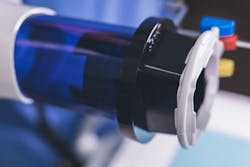
Collimators are an option to reduce patient exposure to radiation. There are both advantages and disadvantages to round and rectangular collimators, as well as short and long position-indicating devices (PIDs). With the use of rectangular collimation versus round collimation, the difference is 60% less radiation exposure to the patient (figure 2).2
Figure 2: A rectangular collimator helps focus an x-ray beam and reduce patient exposure to radiation. In this picture, the XCP-ORA ring is attached to the collimator.
However, the rectangular collimator is only slightly larger than a size 2 receptor, meaning alignment of the PID to the image receptor is critical. With a smaller margin for error, the potential for operator error increases. Conversely, the round collimator is significantly larger than a size 2 receptor, leaving more room for operator error but more radiation exposure to the patient. As far as the PID shape and sizing, 8-inch and 16-inch position-indicating devices are available in rectangular and round. The longer, rectangular PID is the best option providing the least amount of patient radiation exposure and less divergence of the beam.2
Receptor selection
Digital radiography provides the convenience of electronic images while reducing radiation exposure to patients. Depending on the digital sensor being used, there is a 50% to 90% decrease in radiation exposure.2 Phosphor storage plates (PSPs) and sensors have become somewhat of a norm. With that said, care instructions and placement are slightly different. When it comes to sensor care, careful handling and proper cord management are two essential parts of maintaining sensor longevity. Phosphor storage plates should be handled with care to avoid scratching or damage to the plates.
Sensors come in sizes 0, 1, and 2. To maximize the information captured in each radiograph, select the largest sensor possible while considering individual patient anatomy. The downside to digital imaging is that clinicians report taking a higher number of retake images. The higher rate of retakes may be due to the ease of taking a digital image versus an analog image.5
Receptor PLACEMENT
There is a significant difference between placing a sensor and placing a film or PSP receptor in the patient’s mouth. A sensor is larger and more rigid, and it is not as flexible as film and PSPs. Depending on the patient, this challenge may add a level of complexity to proper receptor placement.
The two most common techniques for taking radiographs are paralleling and bisecting angle. Both have different applications and are very effective when used appropriately. The paralleling technique is considered the gold standard. It may be used with a wide variety of aiming devices. It’s important to choose an aiming device that works best for the specific type of receptor.
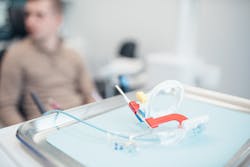
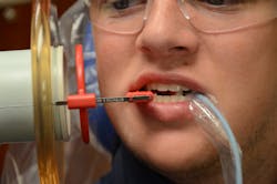
Clinicians have many choices when it comes to holders and aiming devices. Some are autoclavable while others are designed as single-use disposable. For example, the XCP-ORA three-in-one positioning system from Dentsply Sirona (figures 3 and 4) is an excellent autoclavable option when using the paralleling technique. This system can be used with film, PSP, and sensor receptors, as there are two types of bite blocks designed to fit each type of receptor. The XCP-ORA three-in-one positioning system allows the clinician to take anterior, posterior, and bitewing images all with one arm and one ring (figure 3). This ring is ideal for use with a rectangular collimator. Its universal colors help with organization and help teach those who are new to intraoral radiography.
Figure 3: XCP-ORA arm and ring (Dentsply Sirona)
Paralleling Technique
The paralleling technique is the technique of choice due to the reduced likelihood of operator error and image distortion. When using this technique, the receptor is placed parallel to the long axis of the tooth, and the PID is then aligned perpendicular to the receptor. When placing sensors for anterior periapical images, it is essential to place the sensor as far away from the teeth as possible but maintain parallelism to the long axes of the teeth. Size 1 or 2 sensors can be utilized in the anterior region depending on the number of images. Using cotton rolls above or below the bite block can be very helpful to prevent cutting off incisal edges of anterior teeth.
When discussing posterior periapical images, the premolar image seems to be the most challenging. With this image, we are to capture the distal of the canine, first premolar, second premolar, and mesial of the first molar.
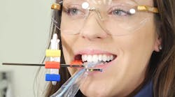
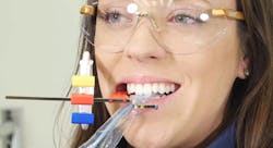
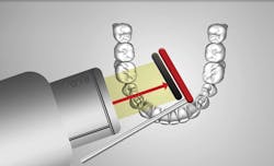
So, how do we capture the distal of the canine but still have open contacts? One option is to place the receptor toward the midline so the pupil of the patient’s eye aligns in the center of the aiming ring. The open-the-door method is another option for mandibular premolar images. After placing the receptor, move it approximately 15 degrees distomesial to capture the distal of the canine but maintain open contacts (figure 4).
Figure 4: Demonstration of the open-the-door method
Bisecting angle Technique
The bisecting angle technique is the other commonly used technique. Bisecting does not require an aiming device; however, more errors result from this technique. Since there is not an aiming device, the vertical angulation of the PID must be adjusted to capture a quality diagnostic image.
When preparing to take an image using the bisecting angle technique, the receptor is placed in the mouth at an angle to the long axis of the tooth. The central beam is then directed perpendicular to an imaginary line that bisects the angle created by the receptor and long axis of the tooth.
This can make it more difficult to achieve a diagnostic image. The positive: This technique is great for patients who have tori, a narrow or shallow palate, or even a gag reflex. This is because the receptor is placed closer to the teeth being exposed rather than further away. The negative: This technique leads to a greater chance of distortion, especially foreshortening and elongation. This is due to having to imagine the divide between the receptor and teeth. A foreshortened image results when the vertical angulation is too steep. To correct this, decrease the vertical angulation. As opposites, elongated images occur when the vertical angulation is too flat. To correct, increase the vertical angulation.2
Bitewing troubleshooting
Bitewing images are probably the most commonly taken radiographs in dentistry. They are usually taken every 12 to 24 months, depending on the patient’s risk factors. Bitewings images help us view interproximal caries, calculus, and other pathology.
Our primary goal is to have open contacts for these images, so proper positioning is critical. The central x-ray beam should be parallel to the interproximal spaces. This will eliminate the chances of overlap and ensure open contacts. For the premolar bitewing, it is expected that the distal of the canines are present. To capture this, use the open-the-door technique described previously.
Challenges may also arise for bitewings. In the presence of mandibular tori, place the receptor behind the tori, allowing more comfort for the patient. The use of bitewing tabs is also an option if a patient presents with a shallow palate. When using the bitewing tab technique, the PID should be aligned at positive 10 degrees, meaning the PID will be pointing downward. Finally, if the patient is missing teeth, cotton rolls may be used in edentulous areas to help stabilize the receptor.
Handheld units
Handheld x-ray units have become more and more popular. Research shows that when used correctly, there are no additional risks for exposure to the clinician.1 However, there is some concern that these units are not always used according to manufacturers’ directions. Handheld units should be held at the mid-torso height to benefit from the safety effects of the backscatter shield. If clinicians hold the handheld device outside the “safe zone,” they are at risk for radiation exposure.6 Aiming devices are available for handheld devices to prevent operator error. Dentsply Sirona’s XCP-ORA short indicator arms do not interfere with the backscatter shield and allow proper alignment to the patient’s face (figure 5). The universal color-coded pins are helpful and may be used with sensors, PSPs, and film biteblock receptors.
Figure 5: The short arm of the XCP-ORA does not interfere with the back scatter shield.
Other considerations
In addition to being aware of accommodations for missing teeth, bony growths, and narrow or shallow palates, it is also essential to work in a sequence. To minimize the potential for patient gagging, begin by taking the most anterior image. If you are taking a full-mouth series, start with anterior periapical images. For bitewings, begin with the premolar bitewing over the molar bitewing. This will help the patient be more compliant as the procedure continues.2
SUMMARY
Radiographs are an essential part of the routine visit to the dental office. As dental professionals, one of our primary goals is patient safety. When taking radiographs, this means following the guidelines for ALARA and proper patient shielding. Dental hygienists play a huge role in obtaining diagnostic images to prevent disease. There are so many options when it comes to receptors, aiming devices, and techniques. Use the tips and tricks provided to capture quality diagnostic radiographs on the first exposure!
References
1. American Dental Association Council on Scientific Affairs; US Department of Health and Human Services Public Health Service; Food and Drug Administration. Dental radiographic examinations: recommendations for patient selection and limiting radiation exposure. Chicago, IL: American Dental Association; 2012.
2. Iannucci JM, Howerton LJ. Dental radiography: principles and techniques. 5th ed. St. Louis, MO: Elsevier; 2017.
3. National Council on Radiation Protection and Measurements. NCRP report no. 145: radiation protection in dentistry. Bethesda, MD: National Council on Radiation Protection and Measurements; 2003.
4. Johnson KB, Ludlow JB, Mauriello SM, Platin E. Reducing the risk of intraoral radiographic imaging with collimation and thyroid shielding. Gen Dent. 2014;62(4):34-40.
5. van der Stelt PF. Better imaging: the advantages of digital radiography. J Am Dent Assoc. 2008;139(Suppl):7S-13S.
6. Makdissi J, Pawar RR, Johnson B, Chong BS. The effects of device position on the operator’s radiation dose when using a handheld portable x-ray device. Dentomaxillofac Radiol. 2016;45(3):20150245.
Editor’s note: This article is supported by Dentsply Sirona.
